UNIT 302
Of The NVQ 2356-99
Diagnose and Correct Faults in Electrotechnical Systems and Equipment
On this page we walk you through everything you need to know to get started – and complete – Unit 302 of your NVQ 2356-99.
What are the ‘Performance Objectives’?
The performance objectives are the criteria of the Electrical NVQ 3 which you are being assessed against. In order to successfully achieve this NVQ, you must meet the performance objective of EVERY unit.
How do I meet the performance objective of every unit of this NVQ?
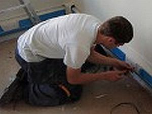
You will simply describe HOW you carried out your duties, WHAT you did and how they related to EACH performance objective. You need to be specific and relate the duties you carried out to the performance objective. You will also need to support this with appropriate photo/video evidence to support your Site Diary/Logbook.
What is Unit 302 wanting me to demonstrate?
This unit – Diagnose and correct faults in electrotechnical systems and equipment – is about you ensuring the safe identification of faults, and correcting the faults by using safe and approved methods. You need to show that you possess the skills and knowledge to follow correct procedures in identifying the location of the fault, carry out safe and secure isolation procedures, diagnose the faults in the electrotechnical systems and equipment, correct faults using safe and use test equipment and tools correctly.
See an overview of this units performance objectives and examples of evidence below.
You personally need to be in as many photos / videos as possible.
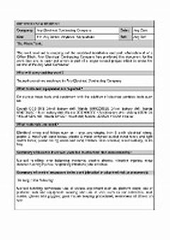
Logbook / Site Diary: One of Three
Insert Site address and brief description of the job you were carrying out.
For example, 120 Any Street, Anytown, Any Postcode. Fault diagnosis and rectification of open circuit on rinf final circuit (date you started and finished particular task).
Remember, this is just an example for your NVQ 3 Electrical, you are advised to consult with your assessor to determine the exact types of evidence they require.
Unit 302 Performance Objective No 1:
You obtain clear and detailed information about the faults including the system specification relating to the electrotechnical systems and equipment.
(You need to describe how you each performance objective, in this case how you went about identifying the fault, see example below)
“Before I started this task I had been given the relevant information from my supervisor. He had informed me that he had been testing one of the ring final circuits before energising this circuit and had noted that the CPC had no reading indicating an incomplete ring.
“I obtained the drawings for the circuit from my supervisor noting the amount 13amp socket outlets on this circuit. I also tested the legs of this ring circuit myself and noted the same results that my supervisor had described. I immediately determined that there must be a disconnected CPC in one of the socket outlets of this circuit and agreed with my supervisor that I would go about correcting this fault.”
Unit 302 Performance Objective No 2:
You advise the relevant people clearly & accurately about the potential disruption and consequences of carrying out a diagnosis and correction of faults.
“As this circuit had not been energised there was no potential disruption to anyone with regard to interrupting the supply etc. Under different circumstances I would inform those who would be affected by the interruption of the supply and give them adequate time and notice of how long the supply would likely be interrupted as outlined in our company policy. This would then give them time to turn computers off and save their work for example.
“In this instance, I had to inform the other electricians that were working in the area that I would need access and that this would take approximately half an hour to resolve. I informed them that I would be coming to and fro and that once this fault had been rectified I would no longer be disrupting their work as they were pulling in SWA. They agreed to put this off until I had rectified the fault and retested the circuit.”
Unit 302 Performance Objective No 3:
You agree the appropriate repairs and their implications with the relevant people in accordance with organisational procedures.
“I agreed with my supervisor that I would correct the fault and retest the circuit upon completion. As this was a new installation there would be no cost implications to the client for the diagnosis and repair of this fault.
“Under other circumstances where I had been called out to repair a fault I would agree the repairs with the client and advise them of the cost implications giving them a choice to agree to go ahead with the work which would normally be carried out using a day-work sheet which would include the time spent and cost of materials etc in accordance with my company’s procedures for reactive maintenance.”
Unit 302 Performance Objective No 4:
You conduct an assessment of safe working practices and perform suitable tests on the installed electrotechnical systems and equipment, safely to identify the fault.
“I completed a risk assessment identifying any hazards and risks associated to the task and co-ordinated the document with my method statement which detailed how to perform the task safely to identify the fault using the correct equipment and PPE. As this was a new circuit there was no need to safely isolate the circuit before fault diagnosis as the circuit had not yet been energised. However, as outlined below, safe isolation had been carried out to the existing supply for the CCU for the refurbishment as outlined below.
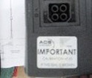
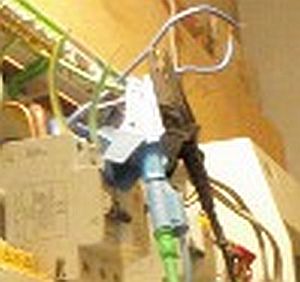
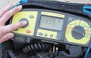
“I checked the test instrument ensuring that the meter and leads were in in good working order before use. For example, I ensure that the leads were robust and met the requirements of GS38. I ensured that the test equipment was in calibration and began to identify the location of the fault using a logical approach.
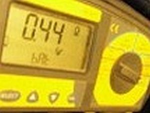
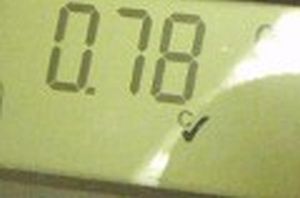
“Although my supervisor advised me of the fault I carried out a continuity of ring final circuit test and obtained reading of 0.45 Ohms and 0.44 Ohms for the phase and neutral, but found there was an open circuit on the CPC.”
Unit 302 Performance Objective No 5:
You follow the correct procedures for carrying out a safe and secure isolation where required, before diagnosing and correcting the fault.
“The circuit in question did not require safe isolation has it had not yet been energised with it being a new circuit. However, this single phase consumer unit, which was to feed the ring final circuit had been isolated beforehand.
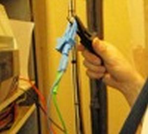
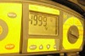
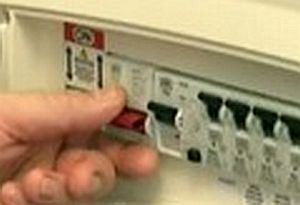
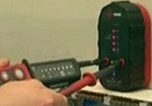
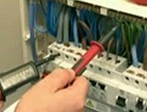
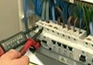
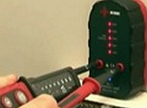
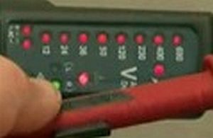
“Safe isolation was carried out using a proving unit and approved voltage indicators as outline in the evidence. To do this, I used a locking device, to which I had the only key, placed a warning notice and checked the circuits were dead with my tester then proving that the tester was still in working order.”
Unit 302 Performance Objective No 6:
You follow correct procedures when rectifying the fault, including using the appropriate tools, equipment and materials.
“I checked the test instrument ensuring that the meter and leads were in in good working order before use. For example, I ensure that the leads were robust and met the requirements of GS38. I ensured that the test equipment was in calibration and began to identify the location of the fault using a logical approach.
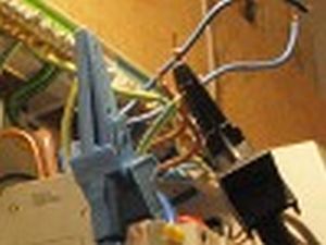
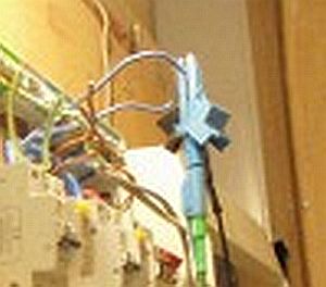
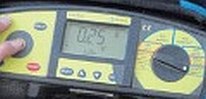
“I temporary connected P1 to E1 and P2 to E2 at the source and then used the drawing to determine the mid-point of the circuit. I then removed the socket outlet and tested between P-E on both legs of the ring at the socket outlet. One leg gave a low reading of 0.25 Ohm’s indicating that this was not the faulty leg and the other leg showed no continuity, indicating that this leg was the fault leg of the ring. With this information I was able to determine the fault lay on one section of the circuit and put a temp connection on the faulty leg between P-E and went further round the ring and repeated this process until I determined which socket outlet had the fault.
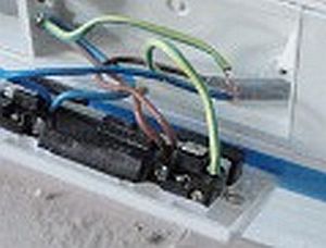
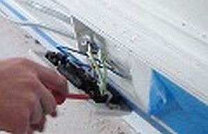
“I noted that the fault was as I suspected and that the CPC had not been connected correctly and had come out of the socket. I re-terminated the CPC, replaced all socket outlets and began testing the circuit again at the consumer unit and tested each socket during the continuity of RFC with satisfactory results. I further tested insulation resistance, polarity, loop impedance, RCD test and functional test and recorded the results and passed these onto my supervisor. All tests complied with BS 7671.”
Unit 301 Performance Objective No 7:
Where the fault cannot be corrected immediately, you leave the electrotechnical systems and equipment safe in accordance with industry regulations.
“On this occasion I was able to immediately identify and rectify the fault, however, should I have not been able to do so, I would had made sure that I did not energise this circuit and would have left the circuit safe until the fault could have been rectified.”
Unit 302 Performance Objective No 8:
You inspect and test that the repaired electrotechnical systems and equipment are functioning in accordance with relevant Industry Standards and specifications.
“Once I rectified the fault I completed an Installation Certificate as this was a new installation and carried out a continuity test, insulation and resistance, polarity, earth fault loop impedance, RCD and functional test. All the results complied with BS7671 wiring regulations.”
Key Criticals
Remember Key Criticals need to be covered OVER the three occasions and NOT in each logbook.
Three electrical systems
LV Single-phase
Although you may have worked on 3 phase, you need to put in the system where the fault lay, in this case it was a LV Single-phase.
Three electrical faults
Incomplete rings
Simply describe the evidence that you have collected for this fault indicating an incomplete ring final circuit.
Additional Evidence
Witness Testimony
Your witness testimony should be from an occupationally competent person such as your chargehand or supervisor. They should be familiar with the national occupational standards to which you are being assessed against and will be contacted by your assessor to validate the testimony provided.
You should not rely on witness testimonies as your main source of evidence. These are provided to support your photo/video evidence and your written account within your logbook. Your main source of evidence will be your photos / videos, so make sure you collect relevant evidence that are appropriate and clearly show you undertaking the tasks that you have described.
Make Completing Your NVQ 2356-99 Quicker And Easier…
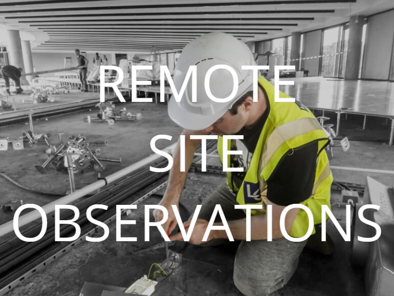
Your assessor can carry out a direct observation of you without the need to physically visit your site. Find out more…
Your assessor will help to build your portfolio for you using the information you provide. Find out more…
Still Have Questions About Your NVQ Level 3 Electrical?
Whether it’s about your previous experience and qualifications in the industry, the difference between the NVQ 2356 & the 2357, or you’re unsure whether the on-site or online path may be best for you, then please do get in touch. We’d be happy to help if we can.
Email Us
enquiries@xstraining.com
Call Us
01535 657059
